
If you work with metal in any capacity, understanding how welding machines work is one of the most practical things you can invest time in. Whether you are a distributor sourcing welding equipment for your regional market, a workshop owner evaluating new machine purchases, or an engineer specifying tools for a production line, knowing the working principles behind different welding machines helps you make more informed decisions, communicate with suppliers more effectively, and troubleshoot problems faster.
This article explains the fundamental science of how a welding machine works, walks through every major welding process and the equipment that powers each one, compares their strengths and limitations, and covers the components, maintenance, and selection criteria that matter in real-world applications. We have aimed to be thorough without being academic — everything here is written from the perspective of people who manufacture and use welding equipment every day.
The Fundamental Principle: How Does a Welding Machine Work?
At its core, every welding machine performs a single function: it converts electrical energy from a utility power source into a controlled output that generates enough heat to melt and permanently join metal. The specific mechanism varies by machine type, but the underlying physics remains consistent across all arc welding processes.
A welding machine takes standard input power — single-phase or three-phase AC at 110V, 220V, 380V, or 440V depending on the region — and transforms it into a lower-voltage, higher-amperage output suitable for welding. The welding arc forms when electrical current jumps across a small gap between the electrode (or welding wire) and the workpiece. This arc generates temperatures typically between 3,000°C and 20,000°C, which is more than sufficient to melt steel, stainless steel, aluminum, copper alloys, and most other industrial metals.
There are four key electrical parameters that a welding machine must control to produce a usable weld:
• Voltage: Governs the arc length and arc stability. Most arc welding processes operate between 10V and 40V at the arc.
• Amperage (welding current): Determines the quantity of heat delivered to the workpiece and the depth of penetration. Typical welding currents range from 5A for delicate TIG work on thin foil to over 500A for heavy structural welding.
• Polarity: The machine can output DC electrode positive (DCEP), DC electrode negative (DCEN), or AC. Polarity selection affects penetration profile, heat distribution, and electrode consumption rate.
• Waveform and frequency: Modern inverter welding machines can shape the output waveform — pulsed DC, variable-frequency square wave AC, and other patterns — to optimize arc characteristics for specific materials and joint types.
The way a welding machine handles this conversion internally defines its generation of technology. Traditional transformer-based welding machines step down voltage and step up current using large copper-and-iron transformers operating at mains frequency (50Hz or 60Hz). These machines are robust and simple, but heavy, often weighing 80–150 kg for a 300A-rated unit. Inverter-based welding machines, which dominate the market today, first rectify mains power to DC, then use high-frequency transistor switching circuits (typically 20–100 kHz) to transform the power. Because the transformer operates at high frequency, it can be physically much smaller. A 300A inverter welding machine may weigh only 10–15 kg while offering equal or better performance. Inverter machines also react faster to arc changes, resulting in smoother, more stable welding output.
Types of Welding Machines and How Each Welding Process Works
Different metalworking tasks demand different welding processes, and each process requires a welding machine specifically engineered for that method. Below, we explain how each type of welding machine works in practical detail.
2.1 MIG Welding Machines (GMAW / Gas Metal Arc Welding)
A MIG welding machine works by continuously feeding a solid metal wire electrode from a spool, through a cable liner, and out of a welding gun into the arc zone. The wire acts as both the electrical conductor that sustains the arc and the filler metal that builds up the weld joint. A shielding gas — typically 75% argon / 25% CO₂ for mild steel, or pure argon for aluminum — flows through the gun nozzle to protect the molten weld pool from atmospheric contamination by oxygen and nitrogen.
Inside the MIG welding machine, a constant-voltage (CV) power source maintains the set arc voltage. A separate wire feed motor, controlled by the machine’s electronics, drives the wire at a speed proportional to the welding current. When the welder increases wire feed speed, more current is drawn to melt the faster-arriving wire, and vice versa. This self-regulating relationship between wire feed speed and arc voltage is what makes MIG welding relatively easy to learn and highly productive. Modern MIG welding machines often include synergic modes, where the operator selects the wire type and diameter, and the machine automatically calculates optimal voltage and wire feed speed combinations.
MIG welding machines are the workhorse of production welding. They are widely used in automotive body panel assembly, structural steel fabrication, shipbuilding, agricultural equipment manufacturing, and general metal fabrication workshops. A typical MIG welding machine for industrial use operates in the 200A–500A range and can deposit 3–8 kg of weld metal per hour, depending on wire size and welding parameters.
TIG Welding Machines (GTAW / Gas Tungsten Arc Welding)
A TIG welding machine works on a fundamentally different principle from MIG. Instead of feeding a consumable wire into the arc, TIG welding uses a non-consumable tungsten electrode to generate the arc. The tungsten electrode has the highest melting point of any pure metal (3,422°C), so it can sustain the arc without melting itself. The welder manually feeds a separate filler rod into the weld pool with one hand while manipulating the TIG torch with the other. Pure argon shielding gas protects both the tungsten electrode and the weld pool.
The TIG welding machine provides a constant-current (CC) output. The welder controls the amperage in real time, typically using a foot pedal or a torch-mounted thumb control. This gives the operator precise, moment-by-moment control over heat input — a critical advantage when welding thin materials (down to 0.5 mm thickness), joining dissimilar metals, or performing root passes on pipe welds where burn-through must be avoided.
TIG welding machines with AC output are essential for aluminum welding. During the electrode-positive half cycle of AC, the arc breaks up the tenacious aluminum oxide layer on the surface (a process called cathodic cleaning). During the electrode-negative half cycle, the arc delivers most of the welding heat for fusion. Advanced AC TIG welding machines allow the operator to adjust AC frequency (from 20 Hz to 400 Hz), AC balance (the ratio of EN to EP time), and waveform shape, giving exceptional control over bead profile and heat input. DC TIG is used for steel, stainless steel, titanium, copper, and nickel alloys.
TIG welding is slower than MIG but produces the highest quality welds with the best appearance. It is the standard process in aerospace, food and pharmaceutical equipment fabrication, nuclear piping, and art metalwork.
Stick Welding Machines (SMAW / Shielded Metal Arc Welding)
A stick welding machine is the simplest form of arc welding equipment. It works by passing welding current through a consumable electrode — a metal rod coated with a layer of flux material. When the welder strikes the electrode tip against the workpiece, an arc forms. The intense heat of the arc melts both the core wire of the electrode and the metal at the joint. Simultaneously, the flux coating decomposes, producing a gas shield that protects the molten metal from the atmosphere, and a layer of slag that covers the solidifying weld bead and slows its cooling rate.
Inside the stick welding machine, the power source provides a constant-current (CC) output, meaning the machine maintains a set amperage even as the arc length (and therefore voltage) varies during welding. This is important because in manual stick welding, the operator cannot keep the electrode-to-work distance perfectly constant. The CC characteristic allows for natural hand movement without drastic changes in welding current.
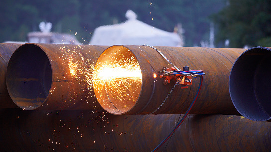
Stick welding machines can output DC, AC, or both. DC output generally produces a smoother, more stable arc and is preferred for most electrode types. AC output is used with specific electrodes designed for AC operation and is common in less expensive machines. The major advantage of stick welding is its simplicity and portability: no external shielding gas cylinder, no wire feeder, and no complex torch assembly. This makes stick welding machines ideal for outdoor field work, pipeline welding, structural steel erection, underwater welding, and maintenance repair in remote locations.
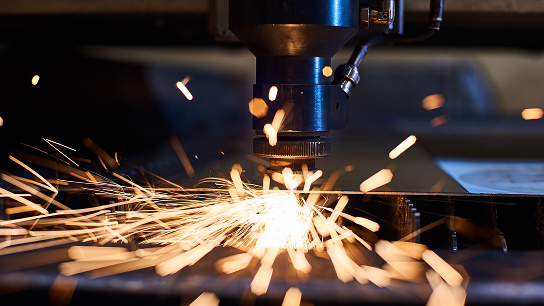
Plasma Cutting Machines
A plasma cutting machine works by a distinctly different mechanism from welding machines, though many of the electrical principles are similar. The machine forces a gas — typically compressed air, but also nitrogen, oxygen, or argon-hydrogen mixtures for specialized applications — through a constricted nozzle orifice at high velocity. Simultaneously, an electrical arc is struck between a tungsten or hafnium electrode inside the torch and the nozzle tip (pilot arc), which ionizes the gas and converts it into plasma. Plasma is sometimes called the fourth state of matter — a superheated, electrically conductive gas that can reach temperatures above 20,000°C.
When the plasma jet contacts the workpiece, the arc transfers from the nozzle to the metal (transferred arc mode), and the main cutting current flows. The extreme heat of the plasma arc melts the metal, while the high-velocity gas stream blows the molten material out of the kerf, producing a clean cut. Inside the plasma cutting machine, the power source provides a constant-current DC output, and the gas delivery system precisely regulates pressure and flow rate. The torch consumables — electrode, nozzle tip, swirl ring, shield cup, and retaining cap — are designed to work together as a matched set for optimal cut quality.
Plasma cutting machines range from compact 20A handheld units for maintenance work to large 200A+ systems mounted on CNC gantry cutting tables for production plate cutting. Cut capacity ranges from sheet metal up to 50–60 mm thick steel plate, depending on the machine’s power rating. Modern plasma cutting machines with precision nozzle technology can achieve cut quality that rivals laser cutting on materials up to 12 mm thick.
Laser Welding Machines
A laser welding machine works by concentrating a high-energy laser beam onto a very small spot on the metal surface. The energy density at the focal point is so high that it melts and fuses the metal almost instantaneously. Fiber laser sources are the dominant technology in modern laser welding machines, offering excellent beam quality, electrical efficiency (typically 30–40% wall-plug efficiency), and minimal maintenance compared to older CO₂ laser systems.
Handheld laser welding machines have emerged as a major category in recent years, making laser welding accessible beyond traditional automated production lines. A typical handheld laser welding machine uses a 1,000W to 3,000W fiber laser source. The laser beam travels through a fiber optic delivery cable to a lightweight handheld welding head. The operator points the beam at the joint and moves along at speeds of 2–5 meters per minute — significantly faster than TIG welding on comparable joints. The heat-affected zone is very narrow, resulting in minimal distortion, reduced discoloration, and little to no post-weld grinding or cleanup.
Laser welding machines are increasingly used in sheet metal fabrication for enclosures, cabinets, kitchen equipment, stainless steel decorative work, and automotive component manufacturing. They are particularly effective on thin materials from 0.5 mm to 4 mm, where traditional arc welding processes often deliver excessive heat.
Comparison Table: How Different Welding Machines Work and Perform
Selecting the right welding machine requires understanding how each type performs across the parameters that matter most in your application. The table below provides a side-by-side comparison of the five major welding machine types:
| Parameter | MIG (GMAW) | TIG (GTAW) | Stick (SMAW) | Plasma Cut | Laser Weld |
| Current Range | 30–500A | 5–300A | 30–500A | 20–200A | N/A (1–3 kW) |
| Output Type | Constant Voltage DC | Constant Current DC/AC | Constant Current DC/AC | Constant Current DC | Fiber laser beam |
| Shielding | Ar/CO₂ mix gas | Pure Argon | Flux coating on rod | Compressed air / gas | None required |
| Filler Material | Consumable wire | Separate filler rod | Consumable electrode | N/A (cutting only) | Optional filler wire |
| Operator Skill | Low–Medium | High | Medium | Low | Low–Medium |
| Deposition Rate | High (3–8 kg/hr) | Low (0.5–2 kg/hr) | Low–Med (1–3 kg/hr) | N/A | Medium |
| Welding Speed | Fast | Slow | Slow | Very fast (cutting) | Very fast |
| Best Applications | Production, structural | Precision, thin material | Field work, heavy plate | Plate/sheet cutting | Sheet metal, speed jobs |
| Portability | Medium (needs gas) | Low–Med (needs gas) | High (no gas needed) | Medium | Medium (fiber cable) |
| Typical Weight | 25–80 kg | 15–40 kg | 8–30 kg | 10–50 kg | 50–150 kg (source) |
Inside the Machine: Key Components of a Welding Machine
Regardless of whether you are looking at a MIG welding machine, a TIG welding machine, or a plasma cutting machine, most modern welding equipment shares a common set of internal and external components. Understanding these components helps explain how the welding machine works as a system and makes troubleshooting much easier.
• Input power section: Includes the mains cable, input rectifier (converts AC to DC), and power factor correction circuits. Three-phase input is standard for industrial welding machines above 200A.
• Inverter switching stage: The core of a modern welding machine. IGBT (Insulated Gate Bipolar Transistor) or MOSFET transistors switch the DC power on and off at 20–100 kHz, creating a high-frequency AC signal that is fed to a compact, lightweight transformer.
• High-frequency transformer: Steps the voltage down and the current up. Because it operates at high frequency, the transformer core and windings can be much smaller than in a mains-frequency transformer machine.
• Output rectifier and filter: Converts the high-frequency AC back to smooth DC welding output. Filtering capacitors and inductors reduce ripple for a stable arc.
• Control PCB and microprocessor: The brain of the welding machine. Monitors output voltage and current thousands of times per second, adjusting the IGBT switching to maintain the set parameters. Also manages the user interface, stored welding programs, and communication with wire feeders or remote controls.
• Cooling system: Industrial welding machines use either forced-air fans or water cooling circuits to dissipate heat from the power electronics. Duty cycle rating is directly linked to cooling capacity.
• Wire feed mechanism (MIG only): A motorized drive system with pressure-adjustable drive rolls that pulls wire from the spool and pushes it through the torch liner at a controlled speed.
• Gas solenoid valve: An electrically controlled valve that opens the shielding gas flow when the welding arc starts and closes it after a set post-flow time to protect the cooling weld.
• Torch or gun connection: The output terminal where the welding torch, gun, or electrode holder connects to the machine. This carries both the welding current and, in MIG and TIG, the gas and control signals.
Understanding these components is essential when evaluating welding machine quality. The grade of IGBTs, the quality of the transformer core material, the thermal design of the cooling system, and the sophistication of the control software all directly affect how reliably and consistently the welding machine works under demanding production conditions.
Welding Machine Consumables and Torches: How They Work Together
A welding machine does not work in isolation. It is part of a system that includes the torch or gun, consumable parts, shielding gas, and filler material. The torch is the component the welder actually holds and manipulates, and its design has a major impact on weld quality, operator comfort, and operating cost.
Plasma Cutting Torches and Consumables
A plasma cutting torch contains a precisely engineered stack of consumable components: the electrode (which sustains the arc), the nozzle tip (which constricts the plasma jet), the swirl ring (which imparts a spinning motion to the gas for cleaner cuts), the shield cup (which protects the nozzle and focuses the secondary shielding gas), and the retaining cap (which holds everything together). Each of these parts wears with use and must be replaced periodically. The quality and dimensional precision of these consumables directly affects cut quality, consumable life, and operating cost per meter of cut.
Compatible replacement consumables, manufactured to match the dimensional and material specifications of the original equipment, offer a cost-effective alternative to OEM parts without sacrificing performance. For example, plasma consumables compatible with Hypertherm Powermax, Thermal Dynamics, ESAB, Trafimet, Cebora, and other major brands are widely available from specialized manufacturers.
TIG Torches and Wear Parts
TIG torch systems include the torch head assembly, back cap, collet, collet body, ceramic nozzle, and gas lens (for applications requiring improved gas coverage). The torch connects to the TIG welding machine via a cable assembly that carries welding current, shielding gas, and (for water-cooled torches) coolant supply and return lines. Standard TIG torch series — WP-9, WP-17, WP-18, WP-20, WP-26 — cover the full range from light-duty 125A air-cooled applications to heavy-duty 500A water-cooled industrial welding.
MIG Torches and Contact Tips
MIG welding torches, also called MIG guns, connect to the MIG welding machine and deliver the welding wire, current, and shielding gas to the arc. Key consumable parts include the contact tip (which transfers current to the wire), the gas nozzle (which directs the shielding gas), and the gas diffuser (which distributes gas evenly). Contact tip wear is the most frequent consumable replacement in MIG welding. The contact tip must maintain a close fit with the wire for reliable electrical contact; a worn or oversize tip causes erratic arc behavior.
Gouging Torches
Carbon arc gouging torches work with a separate power source (typically a stick welding machine or dedicated gouging machine) and compressed air supply. The torch holds a carbon electrode and directs an air jet to blow out molten metal, creating a groove in the workpiece. This process is used for weld joint preparation, defect removal, and back-gouging of double-sided welds. Gouging torches like the K3, K4000, and FLAIR series are standard equipment in shipyards, structural steel shops, and heavy fabrication facilities.
Duty Cycle and Performance Ratings: What the Numbers on a Welding Machine Mean
When you read the specifications of a welding machine, one of the most important numbers is the duty cycle rating. This tells you how long the welding machine can operate continuously at a given current level within a 10-minute period before it must pause to cool down.
For example, a welding machine rated at 300A with a 60% duty cycle at 40°C means the machine can weld continuously at 300A for 6 minutes out of every 10-minute period. During the remaining 4 minutes, the machine must idle to allow the internal components to cool. If the welder operates at a lower current, the duty cycle increases — the same machine might achieve 100% duty cycle at 250A.
The ambient temperature reference is also critical. Most international standards (such as IEC 60974-1) require duty cycle to be rated at 40°C ambient temperature. Some manufacturers rate their machines at 20°C or 25°C, which inflates the numbers. Always compare duty cycle ratings at the same reference temperature.
Duty Cycle Example: Understanding the Specification
| Rated Current | Duty Cycle @40°C | Welding Time per 10 min | Cooling Time per 10 min |
| 300A | 60% | 6 minutes | 4 minutes |
| 250A | 80% | 8 minutes | 2 minutes |
| 200A | 100% | 10 minutes (continuous) | 0 minutes |
| 350A | 40% | 4 minutes | 6 minutes |
| 400A | 25% | 2.5 minutes | 7.5 minutes |
As the table shows, a welding machine can work at currents above its nominal rating, but only for shorter periods. Conversely, reducing the welding current extends the available welding time. For production environments where the welding machine runs almost continuously, choosing a machine with a 100% duty cycle at your typical operating current is essential to avoid thermal shutdowns and production delays.
Other important specifications include: open circuit voltage (OCV), which must be high enough to reliably start the arc but low enough to comply with safety standards (typically 60–80V DC); power factor, which indicates how efficiently the welding machine draws power from the mains; and efficiency percentage, which tells you how much of the input power is converted to useful welding output rather than wasted as heat.
How to Choose the Right Welding Machine for Your Application
Understanding how each welding machine works is the foundation, but translating that knowledge into a purchasing decision requires evaluating your specific requirements against the capabilities of available equipment. Here is a systematic approach to selecting the right welding machine:
Step 1: Define Your Primary Welding Process
Start with the welding process your work demands most. If 80% of your work is production welding on mild steel, a MIG welding machine is the most productive choice. If you primarily weld stainless steel or aluminum components where appearance and quality are critical, a TIG welding machine is likely essential. If your work involves cutting steel plate to shape before fabrication, a plasma cutting machine is a core requirement. Many workshops need multiple types of welding machines to cover their full range of work.
Step 2: Determine Current and Duty Cycle Requirements
Calculate the welding current you will typically use based on your material thickness and joint type. Then consider how much continuous welding time you need. A maintenance shop that welds intermittently can use a lower duty cycle machine, while a production line running two shifts needs a machine rated for 100% duty cycle at the required amperage.
Step 3: Consider Input Power Availability
Verify what electrical supply is available at your work location. Single-phase 220V limits you to smaller welding machines (typically under 250A). Three-phase 380V or 440V supply is standard for industrial machines and provides higher power capacity and better efficiency. If working on construction sites or in remote locations, generator compatibility may also be a factor.
Step 4: Evaluate the Torch and Consumable System
The welding machine is only as good as its torch system. Check whether the machine uses standard torch connections and consumable formats that are readily available in your market. Proprietary torch designs can lead to supply problems and higher long-term costs. Machines compatible with widely available torch and consumable standards (such as Euro-central connectors for MIG, standard WP-series TIG torches, and Hypertherm-compatible plasma consumables) offer the best flexibility and lowest operating costs.
Step 5: OEM and Private Label Capability
For distributors and brand owners, the ability to source welding machines with your own branding is an important consideration. Many established welding equipment manufacturers offer OEM and private label services, including custom panel graphics, packaging, and product configurations tailored to your target market. This allows you to build your own brand identity while leveraging the manufacturing expertise of an experienced factory.
Welding Machine Safety: How Protective Systems Work
Modern welding machines incorporate multiple safety systems that protect both the operator and the machine itself. Understanding how these systems work is important for safe operation and for evaluating machine quality.
• Thermal overload protection: Temperature sensors inside the welding machine monitor the heat of critical components (IGBTs, transformer, rectifier). If the temperature exceeds a safe threshold, the machine automatically reduces output or shuts down to prevent damage. A well-designed thermal protection system allows the welding machine to operate reliably up to its rated duty cycle without nuisance shutdowns.
• Over-voltage and under-voltage protection: Protects the inverter electronics from damage caused by mains voltage fluctuations. This is especially important in regions with unstable electrical supply or when the welding machine is powered by a generator.
• Over-current protection: If the welding current exceeds safe limits (for example, due to a short circuit at the torch), the machine rapidly limits or cuts the output to prevent damage to the power electronics and welding cables.
• VRD (Voltage Reduction Device): Reduces the open circuit voltage at the output terminals to a safe level (typically below 12V DC) when the machine is on but not welding. When the welder touches the electrode to the workpiece, the VRD detects the change and instantly raises the voltage to start the arc. VRD is mandatory in many countries for stick welding machines used on construction sites.
• IP rating and environmental protection: The enclosure of the welding machine is rated for dust and water ingress according to the IP (Ingress Protection) code. Industrial welding machines are typically rated IP21 to IP23 for indoor use, while machines intended for outdoor use may carry higher ratings.
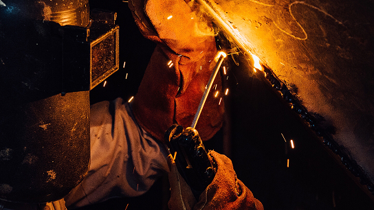
Beyond the machine itself, safe welding practice requires proper personal protective equipment (PPE) including an auto-darkening welding helmet, flame-resistant clothing, welding gloves, and safety boots. Adequate ventilation or fume extraction is essential to protect the welder from breathing harmful welding fumes. These safety elements work together with the welding machine’s built-in protections to create a safe working environment.
Maintenance and Troubleshooting: Keeping Your Welding Machine Working Reliably
Like any industrial equipment, a welding machine requires regular maintenance to deliver consistent performance and achieve its expected service life. Most maintenance tasks are straightforward and can be performed by the machine operator or workshop technician.
Routine Maintenance Checklist
• Clean or replace air filters: Dust buildup restricts airflow through the welding machine, reducing cooling efficiency and potentially leading to thermal shutdowns. In dusty environments, check and clean filters weekly.
• Inspect welding cables and connections: Look for damaged insulation, loose terminal connections, and corrosion. Poor cable connections increase resistance, generate heat, and reduce welding performance.
• Check and replace torch consumables: Worn contact tips, nozzles, and electrodes degrade weld quality before they fail completely. Replace consumables on a regular schedule rather than waiting for failure.
• Verify gas flow and connections: Check for leaks in gas hoses and fittings. Verify that the flow rate matches the recommended setting for your process and material.
• Inspect the wire feed system (MIG): Check drive roll condition and alignment, liner condition, and wire spool tension. A worn drive roll or kinked liner causes erratic wire feed and inconsistent arc behavior.
• Blow out internal dust periodically: Use clean, dry compressed air to remove accumulated dust from inside the welding machine. Always disconnect power first. Focus on cooling fan areas and between heat sink fins.
Common Troubleshooting
When a welding machine does not perform as expected, start with the most common and simplest causes before suspecting a machine fault:
• Unstable or erratic arc: In MIG welding, check the contact tip for wear, verify wire feed tension and liner condition, and ensure the work clamp has a clean connection to the workpiece. In TIG welding, check the tungsten electrode for contamination and ensure the gas flow rate is correct.
• Machine won’t start or trips immediately: Check input power supply, verify that the thermal protection has not been triggered (allow cooling time), and inspect for damaged input cables or blown fuses.
• Poor weld quality despite correct settings: Check consumable condition, gas coverage, workpiece surface cleanliness, and ground connection. Many weld quality problems originate outside the welding machine itself.
• Excessive spatter in MIG welding: Verify voltage and wire feed speed settings, check gas flow rate, and ensure the correct gas mixture is being used. Also inspect the nozzle for spatter buildup that restricts gas flow.
The Future of Welding Machines: Automation, Digitalization, and Connectivity
The welding equipment industry continues to evolve. Understanding current trends helps buyers and distributors position themselves for the future.
Welding robots and collaborative robots (cobots) are becoming more accessible to small and medium-sized fabricators. A welding robot integrates a MIG or TIG welding machine with a multi-axis robotic arm and programmable controller. This combination delivers consistent weld quality at production speeds that manual welding cannot match. Cobots are specifically designed to work safely alongside human operators without safety cages, making robotic welding practical for lower-volume, higher-mix production environments.
Digital connectivity is another major trend. Modern welding machines increasingly offer data logging, weld parameter monitoring, and remote diagnostics through cloud-connected platforms. This data allows fabrication managers to track weld quality, operator performance, consumable usage, and machine utilization in real time. For quality-critical applications, digital weld records can provide full traceability for every weld joint in a structure.
Laser welding technology continues to advance rapidly, with handheld fiber laser welding machines expanding into applications traditionally served by TIG and MIG welding. As laser source costs decrease and power levels increase, laser welding machines are expected to capture a growing share of the sheet metal fabrication market.
For buyers and distributors of welding equipment, these trends mean that the welding machines you source today should not just meet current needs but also fit into an evolving ecosystem of automated, connected, and increasingly laser-based manufacturing technology. Partnering with a welding equipment manufacturer that has the technical depth and product breadth to support this transition is a significant competitive advantage.
Conclusion
Understanding how welding machines work — from the fundamental physics of the welding arc, through the internal architecture of inverter power sources, to the practical details of torches, consumables, and maintenance — gives you a solid foundation for making better equipment decisions. Whether you are comparing a MIG welding machine to a TIG welding machine for a new production line, evaluating a plasma cutting machine for your fabrication shop, or considering the addition of laser welding to your capabilities, the principles covered in this guide apply directly.
The welding equipment industry rewards informed buyers. When you understand how each welding machine works, you can evaluate specifications meaningfully, ask suppliers the right questions, and ultimately choose equipment that delivers reliable performance, reasonable operating costs, and long service life for your specific applications.